


Latest Post

Needs for Twin Chamber Heater
BURNER DESCRIPTION
The Version is for as much as 300kgs capability per batch bunches in addition to will absolutely lose at around 55kgs per hour.
The system has leading packing style and has a strong refractory concrete lining for optimal heat retention. Gadget have huge leading cover for extremely easy loading, along with especially made front ash door, for ash elimination.
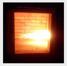
This system performs at over 1100 ° C in the vital chamber to guarantee total combustion. This design likewise benefits
from a strong second chamber as well as burner that makes particular a complete re-burn of any smoke along with exhausts along with a 0.5 second gas retention time.
Thaw rate 150kg/h minimum
Second Chamber Yes.
Gas Retention Time 2 secs.
Gas Diesel/LPG/LNG.
Power Supply for Control Box 220V-240V 50Hz singular phase.
Minimum Operating Temperature Level 920 ˚C
PRIMARY CHAMBER.
Resilient steel case.
Outstanding quality refractory lining as well as insulation.
Substantial full dimension leading lots door and also fluid retention sill.
1 x diesel oil terminated ignition heating systems operated on/off.
EXTRA CHAMBER.
Sturdy steel housing.
High quality refractory lining along with insulation.
1 x diesel oil fired ignition heating units ran on/off.
Requirements for Dual Chamber Incinerator:.
Key Burning.
The primary burning chamber will be approved as the crucial burning area.
The minimum burning temperature of the vital chamber shall not be much less than 800 degrees c.
Additional Burning.
The house time in the second chamber will certainly not be a lot less than 2 secs.
The gas temperature degree as gauged versus the within wall surface in the additional chamber, not in the fire zone will certainly not be less than as suggested in Lot 1-7.
Both the additionally additional as well as primary temperature levels will be maintained till all the waste has actually been completely ignited.
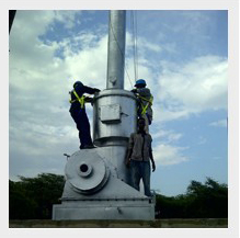
Chimney.
The chimney shall have a very little height of 4 metres over ground level.
The minimal departure rate of the discharges will not be less than 10metres/second.
Temperature Cautions.
When the second temperature level drops to listed below the required temperature level, a distinct and/or recognizable alarm to alert the operator.
General.
Control box can be divided and also installed on different stand of atleast 1.5 metres from the burner at about 1.6 metre altitude.
CE certified or equal for burners of this measurement and additionally design.
Drawings along with images for the provided whole lots.
1 year extra parts, gas containers as well as 10metre pipe ahead typical with every heater.
Specs for Mobile Heater Units.
Trailer mounted mobile burner tools excellent for the following applications.
Clinical waste.
Residential waste.
Industrial waste.
Pet cadavers.
SMOKESHAFT.
Resilient stainless-steel situation.
1.5 m dimension.
0.6 m refractory lined stack.
CONTROL PANEL.
Control of 1 heating unit.
Timer control 0- 12 hrs.
Vital fan timer control.
Temperature level Monitoring.
Thermostatic Control.
Automatic Control.
Cycle time developed.
ANCILLARIES.
Running along with maintenance handbooks.
Saves listing.
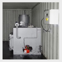
CONTAINERISATION.
incinerator absolutely mounted within 10 ft ISO accredited container.
3,5 kwA electrical power generator, 1000 litres fuel storage tank.
Burner placed on the silenblock padding.

MEDICAL WASTE INCINERATORS
MEDICAL WASTE INCINERATORS for furnishing, installing, adjusting, and testing automatically controlled air medical waste incinerators having a capacity to burn 75 Kg/hour waste materials of biological and pathological nature.
The process of incineration provides the advantage of volume reduction as well as the ability to dispose of recognizable waste and sharps. On site incinerators provide a quick and easy way of disposing medical waste. This is the most widely accepted and feasible method of managing highly infectious waste.
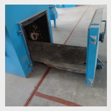
The incinerator will be of the controlled air type, designed for (6-8) hour-day operations and rated at 75 kg per hour. The incinerator plant will include the following:
3Continuous loading using hydraulic ram feeder o Burners and fuel system
o Fans
o Pumps
o Controls and Instrumentation o Chimney and flue connections
o Incinerator loader for loading hoppers or carts o Ash handling equipment
41 year spare parts
5Waste weighing equipment
6Wheeled 2.0m3 waste storage hoppers (number to be decided by hospital managers)
7Incinerator loader
8Incinerator building, including fire safety equipment
9Platform and portholes designed to USEPA standards to facilitate stack testing.
The publications listed below form a part of this specification to the extent referenced. The publications are referred to within the text by the basic designation only.
AIR MOVEMENT AND CONTROL ASSOCIATION INTERNATIONAL (AMCA) AMERICAN SOCIETY OF CIVIL ENGINEERS (ASCE)
AMERICAN WELDING SOCIETY (AWS)
ASME INTERNATIONAL (ASME) Sheet, Cold-Rolled, Carbon, Structural,
High-Strength Low-Alloy and High-Strength Low-Alloy with Improved Formability, Solution Hardened, and Bake Hardened
SECTION 11 82 21 Page 6
ASTM A53/A53M (2010) Standard Specification for Pipe,
Steel, Black and Hot-Dipped, Zinc-Coated, Welded and Seamless ASTM A653/A653M (2010) Standard Specification for Steel
Sheet, Zinc-Coated (Galvanized) or Zinc-Iron Alloy-Coated (Gal annealed) by Hot-Dip Process FM GLOBAL (FM)
ISA – INTERNATIONAL SOCIETY OF AUTOMATION (ISA)
MANUFACTURERS STANDARDIZATION SOCIETY OF THE VALVE AND FITTINGS INDUSTRY (MSS)
NATIONAL ELECTRICAL MANUFACTURERS ASSOCIATION (NEMA) NATIONAL FIRE PROTECTION ASSOCIATION (NFPA)
U.S. DEPARTMENT OF DEFENSE (DOD)
U.S. GENERAL SERVICES ADMINISTRATION (GSA) UNDERWRITERS LABORATORIES (UL)

INCINERATOR TESTING AND COMMISSIONING
A flue chimney, 15,000mm long and 560mm diameter shall be constructed from steel sheet, complete with lagging, damper and rain water protection cone. The chimney shall be lined with castable grade diatomaceous concrete mixed with high alumina cement in accordance with BS 4076: 1989.
The damper will control the closing of the door to not less than 85%. The stack is to allow fresh air at the stock’s base so that the flue gases are discharged at not move then 4000 C and that the discharge conforms to the British Clean Air Act, the National Environment Management Agency (NEMA) Act or other relevant acts. .
1.1.4 POWER SUPPLY
The sub-contractor shall supply equipment which are suitable for running on a 415V, 3 phase, 50HZ or 240V, single phase, 50HZ electric power supply.
1.1.5 OIL STORAGE AND SUPPLY
The system shall consist of a bulk oil storage tank, daily tank, transfer hand fuel pump and associated pipe work. Oil from the bulk storage tank will be delivered to a high level daily tank situated in the incinerator room by use of a transfer hand pump and automatic electric pump.
1.1.6 SPARES AND MANUALS
The tenderer is to submit with his tender a list of recommended initial stock of spares together with their prices. A part from the burner spares mentioned here below, the spares prices are not to be included in the main summary of prices schedule but is to be separate and are meant to be ordered later if and when it becomes necessary and convenient to the client. The burner spares whose prices are to be included in the main summary of prices schedule (BQ) are:-
i) 1No. Set of safety controls
ii) 1No. Solenoid valve
iii) 1No. Oil ignition system
iv) 2No. Photo-electric cells
Two sets of operating and maintenance manuals (both for the incinerator and burners) must also be supplied. This include two sets of control schematic diagrams for all the controls and wiring.
1.1.7 BULK OIL STORAGE TANK
The bulk oil storage tank nominal capacity of 10,200 litres and complying with BS 799 part 5: 1975 shall be positioned on three concrete cradles.
The works shall include supply, delivery, assembling, erection, testing, commissioning and setting to work. The tank is to be of welded mild steel type with a design pressure of 40KN/m2 and storage temperature of 240 C. It is to be located adjacent to the incinerator and boiler house.
The tank shall be cylindrical with dished end and be constructed of 6mm thick block mild steel plates in accordance with BS 1966. Number one quality galvanised materials shall not be used.Welded construction parts shall be sprayed.
E-4
The tank shall be pressure tested with a total head of water or equivalent, measured from the base of the tank, and equal to 1½ times the sum of:
(i) The height of the tank and
(ii) The design head above the top of the tank that is 3.5m of water.
The pressure shall be raised slowly and steadily until the specified test pressure is reached and that pressure shall be maintained for a period long enough to permit a thorough examination to be made to ensure that the tank is sound enough and shows no leaks or undue distortion. Welded joints shall be radiographed and a certificate issued. Should any defects be found, they shall be made good and the test procedure repeated until the tank is certified to be sound. The tests shall be carried out in the presence of the Engineer and subsequently, the sub-contractor will provide the Engineer with the test certificate.
The tank shall then be cleaned externally and provided with rust inhibiting primer before applying 2No. coats of bituminous paint. The inside shall also be cleaned and purged of any foreign matter before setting to work.
Ladders and platforms shall be thoroughly cleaned and freed from rust and scale and painted with a priming coat of approved paint.
The tank shall be provided with the following:-
(i) 450mm bolted inspection covers with liquid and vapour tight joint made with a gasket of fuel resistant materials.
(ii) 75mm (3”) vent socket screwed B-SP and pipe at the higher end of the tank with an unloading device to prevent the rise in tank pressure above the design pressure. The vent pipe shall be free from bends and shall have a continuous rise while being as short as convenient. It shall terminate in open air in a position where it cannot be tampered with. The open end shall be turned down and fitted with an open mesh wire cage.
(iii) 65mm diameter filling pipe with hose coupling connection
(iv) 50mm diameter gauging connection with lockable cap.
(v) 50mm diameter supply pipe
(vi) 25mm diameter water drain-off value
The tenderer shall supply hydrostatic oil contents gauge (level indicator) or a
properly calibrated stick (of dip tape) and access ladder to the top of the tank.
The filling pipe shall be extended inside the tank to within 150mm of tank bottom,
complete with anti-siphoning device.
The following information shall be permanently and clearly marked on the tank on the
centre line near the outlet connection.
• Gross capacity in litres
• Test pressure
• Date of test
• Maximum allowable working pressure
• Manufacturer’s name of trade mark
• Year of manufacture
• The number of British standard and type of tank
The tank shall be installed with a 25mm fall towards the water drain-off tapping point. The supply socket shall be extended inside the tank to prevent ingress of water in the supply line. The main contractor shall construct tank supports and bund walls to detail drawings produced by the sub-contractor. A valued drain off from the lowest part of the tank shall be provided complete with tail pipe and a provision for hose connection.
E-5
1.1.8 TRANSFER HAND PUMP
A semi rotary hand pump shall be provided for filling the day storage tank from the oil drum. It shall be installed complete with all the necessary plumbing fittings and accessories.
1.1.9 DAILY SERVICE TANK
A daily storage tank of nominal capacity 1,800Litres shall be mounted at 2.5 metre high level in the incinerator room. Tank shall be manufactured from 6mm thick pressed steel plates of 1220mm x 1220mm black mild steel sheet, complete with bolted cover and adequate venting. The tank shall conform to BS 799 part 5 1995 and be provided with a contents sight tube. The tank shall be lagged with 50mm thick fibre glass insulation of 0.4W/m2 thermal conductivity and finished with 20SWG galvanized sheets cladding.
The tank shall be tested for any leaks of which if any is detected will be made good before the tank is painted externally with rust inhibiting paint. Tank to be securely bolted.
1.1.10 AUXILLIARY EQUIPMENT
All pipework used in the oil storage systems shall be to B.S. 1387 heavy grade. Joints shall be screwed, and sufficient unions must be provided to allow easy dismantling the equipment.
A 25mm diameter fire valve of the quick action lever operated dead weight type shall be installed, in the oil flow line. This shall be held in the open position by a light gauge steel cable attached to a fusible link. The fusible link shall be mounted directly over the burner. The warm burner oil feed pipe from the high level day tank shall be heated by an electric tracing tape properly wrapped around the pipe. The pipe shall then be insulated with 25mm thick fibre glass insulation and finished with gauge 22swg galvanized steel sheet.
The supply pipe from the bulk oil storage tank to the high level day has been installed by others but the tenderer shall allow for connection to the high level day tank. The tenderer shall also supply and install high capacity strainers along the supply pipe and the burner feed pipe.
1.1.11 PIPE SUPPORTS
The variety and type of supports shall be kept to a minimum and their design shall be such as to facilitate guide and secure fixing to match concrete masonry or wood.
Consideration shall be given when designing supports to the maintenance of desired pipe fall and the restraining of pipe movements to a longitudinal axial direction only.
The sub-contractor shall supply and install all steel work forming part of pipe support assemblies and shall be responsible for making good any damage to builders work associated with builders work installation.
Pipe runs shall be secured by clips connected to pipe hangers, wall brackets or trapeze type supports. ‘U’ bolts shall not be used for clips without prior approval of the Engineer.
The sub-contractor shall submit his entire proposal for the pipe supports to the Engineer for approval before any erection work commences.
1.1.12 ELECTRICAL WORKS
All wiring between items, plant and controls shall be executed by the tenderer. The tenderer shall provide adequate supervision to ensure that electrical connections are correctly made to all items of equipment and controls supplied by him, all to the Project Manager’s / Engineer’s satisfaction.
E-6
1.1.13 INCINERATOR TESTING AND COMMISSIONING
The tenderer shall test and commission the incinerator in the presence of the Engineer.The tenderer shall also provide sufficient oil to last at least two (2) hours. The tenderer shall test and commission the incinerator in the presence of the Engineer and verify that the incinerator is functioning according to the specifications laid here-in and in the catalogues and manuals from the suppliers of he incinerator.The incinerator performance test shall be carried out in accordance to BS3316: part 4:1987.Should any defect be detected, it shall be rectified and the testing process repeated to the Project Manager’s satisfaction.
1.1.14 FIRE INSTRUCTION NOTICE
Proceed and procure and install as below;
Print fire instruction on the Perspex plate, 3mm thick with White Colour
Background measuring 510mm lengthx380mm width as follows;

For incineration, fundamental and likewise pathological burners
Main unit
Application For incineration, general and pathological
Capacity 50 – 60 kg/h burn rate
Type Two combustion chambers type; primary and Secondary, controlled/forced combustion air type with a flue gas emission scrubbing unit
Operating time Minimum 8 hours daily
Operating temperature From 850 0C to 1200 0C, Automatic controlled
Residual Ash 5 to 10%
3.2 Primary Chamber
Construction Constructed from heavy duty mild or aluminized steel Or
equal and approved equivalent
Insulation material Refractory material lining similar or equal to calcium
Silicate and hot face combination of heavy duty brickwork
Internal Construction Fixed hearth type complete with gratings, concave bottom
and charging door, lined with refractory material
Charging Door Suitable for manual loading of wastes and with smooth
Dear seal equivalent of Ceramic seals with hinges.
Door Lock Automatic, Electric type
Ash removal door Provided, for removing resultant bottom ash leftovers from the Primary chamber
Gratings Provided
Loading Manual loading of waste
Primary Burner Fully automatic, with fuel, temperature and speed controls with ignition system, flame detector, Air fan complete with safety features, flame failure, Diesel fired fuel injector type and Flange mounted
Blower Provided. For supplying excess combustion air through the distribution system with speed control system
Temperature Minimum exit 850 0C
Observation port To be provided with protective glass type
3.3 Secondary chamber
Construction Constructed from heavy duty mild or aluminized steel or equal and approved equivalent
Insulation Refractory material lining
Combustion Temperatures Above 850 0C, controlled electronically
Gas residue or retention Time > 2 second at minimum 850 0C
Secondary Burner Provided, Diesel fired, fully automatic, with fuel, temperature and speed controls, With ignition system, Flame detector, Air fan, Complete with safety features, flame failure Diesel fired fuel injector type. Flange mounted
Ejector Provided, Venturi type, for cooling the flue gases
Combustion Air Fan Provided for supplying combustion and creating a negative drift and turbulences
Temperature Maximum 1600 0C
3.4 Chimney
Construction Constructed from heavy duty mild or aluminized steel or equal and approved equivalent Refractory material lining
Length 10 m above ground
Bore about 350mm diameter
Discharge temperatures About 850 0C
Emissions To comply with standards in section 9 of third schedule of the waste management regulations, 2006.
3.5 Electrical System
Control unit Fully automatic with microprocessor based control unit (PLC) automating all operations of the incinerator. Capable of monitoring all incinerator parameters With large LCD or similar for display of all progress
Parameters i.e. temperature of primary and secondary chambers, turbulence and time
With status lamp
With user of defined and differed programmed operating cycles for different type of loads/conditions
With safety interlocks, display of errors and visible and audio alarms.
System for continuous emission monitoring
Isolator switch Supply and install isolator switch 240V, 100A for the incinerator unit, including all necessary cables 10m
Distribution Board Supply and install distribution board. 100 A, complete with MCBs suitable for the rating of the incinerator unit and associated equipment. Wiring to be done according IEE regulations.
Wiring Make provisions for wiring the isolator switch, Distribution Board control unit to Incinerator and all associated equipment inside to incinerator room. Working length 20m. Wiring to be done using PVC Sheath cable on steel conduits and trucking and in accordance with IEE regulations
Fuel System Supply and install storage fuel tank inside the incinerator room at an elevated position (about 1.5 m above the floor)
Fuel Tank Tank capacity, 400 liters, constructed from preferable suitable metallic material or high temperature resistance material
Fuel type Diesel
Fuel Lines Supply and install fuel lines, complete with fuel filters, pump, sight glass, fuel level and all other safety devices and connect from fuel tank to incinerator.
Working length , 20m
Fuel pipe material; Special copper pipes or similar and approved materials
4 Physical characteristics
Main unit Floor mounted, stand alone, fixed hearth type
Dimensions About 1.2 x 2.2m (WxD)
5 Operating environment
Power Requirements 240V,A/C 50Hz, single phase, with PE
Ambient temperature 10 0C to 40 0C
Relatively humidity 40% to 90%
6. Accessories
Rack, 2 m long 1 piece
Waste cart, stainless steel 1 piece
Spare parts
Burner 1 set
Fuel Filters 6 sets
All other spare parts required for replacement during and after 12 months of operations. 2 pieces of each
8 Quality Standards
Manufacturing standards NEMA Kenya Act, 1999
Legal Notice No.121 of 29th September 1999 on waste Management Regulations
EU waste incinerator Directive- EC 76/2000
BS 3316
WHO Emission Standards
World Bank Emission Standards
or any other internationally recognized standards
Conformity to standards CE marked or any other internationally recognized documents
9 Local back up service
Available Should be available locally
Capacity to service equipment Manufacturer/Agent shall have adequate facilities, spare parts, qualified and skilled technical staff to offer comprehensive maintenance service and spare parts sales for the lifespan of the incinerator
10 Delivery point
KEMSA For inspection and verification
Moi Voi, Makindu
Maragua, Eldama Ravine and Isiolo Hospitals For installation, testing, NEMA Certification and commissioning
Pre installation works
Provide for foundation plinth, necessary plumbing works, Fuel piping works, Elevated Diesel oil storage tank, electrical works including cabling, trunking and switch gears required to install the incinerator and all its accessories to required IEE standards
Installation and testing Complete installation and set up of the incinerator at designated as per manufacturer’s instructions
Provide fuel and test run the incinerator for 3 hours daily for 7 days
Training
User training On site user training on operation and daily up keep
Maintenance training On-site maintenance training on Preventive Maintenance, repair and trouble shooting
Technical Documentations
User manuals 2 sets
Service manuals 2 sets
Drawings 2 sets
15 Commissioning
Testing and Commissioning of the machine to the satisfaction of the user
Warranty
Equipment Minimum of one year after commissioning on all parts.
Equipment system Nil
17. Maintenance contract
Comprehensive preventive & repair service Provided a 12 months comprehensive preventive and repair service contract inclusive of spare parts and material from date of commissioning

About Hiclover Medical Enviromental
HICLOVER, Nanjing Clover Medical Technology Co.,Ltd, supply system solutions for medical environmental protection, animal and pet cremation engineering, other municipal solid waste incineration project.
We supply single combustion chamber, double combustion chambers, three combustion chambers and multi-combustion chambers waste incinerators for laboratory, clinic, hospital, medical center, hygiene clinical waste destruction with medical disposable, biological waste, medical plastic waste, hazardous waste, red bag waste, needle disposal, gauze and bandages, sealed sharp containers, pathological waste, trace-chemotherapeutic wastes, etc.
Our range of incinerators cater for small to large scale animal cremation related businesses, such as poultry farms, cattle farms, sheep farms, pig farms, stables, kennels, testing laboratory, catteries, pet crematoriums.
The incinerator burn waste in primary combustion chamber and burn the smoke from primary combustion chamber again to make sure environmentally friendly with no black smoke, smelless, reduce pathogenic bacteria infection.
System solutions for medical waste environmental, including waste incineration, smoke emission treatment, high-temperature sterilization, ultraviolet sterilization lamp, waste shredder, needle destroyer, medical waste package, sharp containers, etc.
The pet cremation equipment humanized design with movable platform, small space covers for modern pet cremation business owner all over the world.
The containerized mobile incinerator mounted in ISO container before leave factory, pre-installation, no incineration house build construction, movable by truck and ultraviolet lamp sterilization inside.
HICLOVER is growing brand for environmental protection field, and market share with most of Africa, Middle East, Southeast Asia countries and part of North America, Europe territory. We a re trusted partner for governmental organizations, non-profit organizations, international contractors, logistics organizations, military, pet cremation business owners, etc. We have export experience more than 40 countries, including war zone like Iraq, Afghanistan, Somalia, South Sudan.
We are china incinerator manufacturer, contractor and exporter. Manufacturer make reasonable price for incinerator customer, supply medical incinerator, hospital incinerator, animal incinerators, hog incinerators, pet cremation equipment, small incinerator, pet incinerator, animal incinerator, portable incinerator, small animal incinerator, infectious waste pyrolysis machine, laboratory incinerator. HICLOVER help customer reduce purchase budget, custom made function, quality products and friendly service.