- Burning rate: 250 Kg/hr.
- It should be able to Operate not Less than 10 hours/day
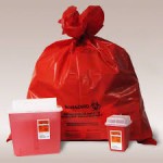
- This incinerator must be able to destruct all combustible wastes produced by hospitals, private clinics, laboratories, institutes, etc…
- Design Specification: Types A, B, C, D, and E of medical waste
- “PYROLYTIC” combustion, by controlling the gasification of waste.
- The incinerator must avoid the release of black smoke and fine dust, (Smokeless) during the loadings.
- It should be able to reduce the volume of wastes by 98%.
- It should be able to hold emission in the second burn with gas residence of not less than 2 seconds.
The incineration should be completely free from visible smoke as well as offensive odours.
- The lower calorific power (L.C.P) of this waste will be 3,500 kcal/kg
- The Temperatures of combustion:Minimum will be 850oC and max 1400oC
- Post combustion: >1100o
- The Internal diameter of the Chimney: Ø 400mm² and its height: 8 Meter
- The Volume of the combustion chamber: Not Less Than 2.3 M³
- Burner operation should be Automatic On/Off
- Fuel : diesel, LPG, Natural Gas, Bio fuel
- The supplier must provide necessary information for the best of the installation
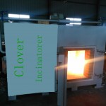
This incinerator with “PYROLYTIC” combustion must have:
- A combustion chamber of waste:
* Perfectly tight door for the manual loading of waste.The loading should be Manual, Batch Load,
* A burner of lighting which the use is limited to the ignition of waste.
* Top Loading loading with door seals gone up on hinges, wheel of screw plug, flexible joint, and stuffing insulating out of refractory.
* The insulation of the combustion chamber should be composed of refractory bricks, having a high content of aluminum and insulates bricks in order to assure a minimum temperature on the outside sheet metal.
* Composition of the refractory;
- Refractory concrete :
- . Thickness : ≥100 mm
- . Nature: 42% of Al203
- Insulate in fibrous panels :
- . Thickness: ≥75 mm
- Nature: Calcium silicate.
* Burner of lighting of waste, with fuel, standard mono-bloc casting guiding plunging flame, lighting and safety of electronic ignition, permanent ventilation, electromagnetic sluice gate of regulation and isolating valve.
* Plate of combustion in Carborundum, avoiding the fixing of glass and slags.
- Load Method: Top Loading
- A chamber of post combustion of gases
* A burner of combustion of gases,
* A device of injection of air allowing a total recombustion of gases,
* A device of air inlet of cooling of waste gases,
* A sheath of evacuation of the gases burnt.
* Carcass in strong sheet steel with support of connection.
* Composition of the refractory;
- Refractory concrete :
- Thickness : ≥180 mm
- Nature: 65% of Al203
- Insulate in fibrous panel :