Category Archives: incinerator-uae
Medical Incinerator Specification
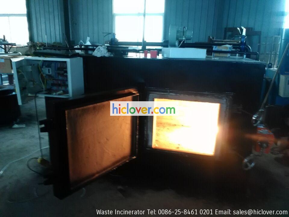
Capacity Not less than 500Kg/hr.
Operation 24hr-7days/week continuous operation.
Combustion chamber 2 combustion chamber.
Temp. First combustion chamber 800-1000 C.
Secandry combustion chamber 1000-1200 C, with the possibility to be upgraded to 1400 C.
Combustion Efficiency 99.99%
Retention time Of the flow gases not less than 2 Sec in the hot portion.
Excess Oxygen concentration Of primary combustion chamber 3-6% max.

Refractory The chambers should be lined with high thermal insulating refractory bricks with suitable thickness and with highly temp.
resistance. Not less than 1400 C for the first combustion chamber, and not less than 1600 C for the secandry combustion chamber, and at the
same time prevent the Temp. of the outside body of the chamber not higher than 70 C.
Doors Should be lined with the same bricks, and the edges lined with special suitable insulating material to prevent any gas escaping, and
the doors should be kept under negative pressure during the operation.
Air Emission Control System With high destruction and removal efficiency (DRE). Not less than 99.9999 as per KEPA.
Wet System If the system equiped with a CEMS washing the flow gas with water, then it should be manufactured from suitable anti
corrossion materials, and equiped with pH meter to measure and neutralize the water. It should be able to use the water in closed recycled
circuit many times before treating/ discharging into the sewage system in compliance with KEPARS.
Chemical dosing It should be equiped with suitable autochemical dosing system to control the pH for the water of the wet scrubber system
including sensors.
Chimney It should be suitable with the capacity and the technical specifications, with height not less than 12m from ground level. With easy
opennable sampling point equal about 3 inch, and the optimum sampling locations is at least 8D downstream direction and 2D upstream from any
flow disturbancies.
Sampling point Should be equiped with a platform located down the sampling point by a distance not less than 1 m, and equiped with suitable
stairs from ground to the port with comfortable slope.
Ash Removal It should be auto ash removal system.
Fuel It should be dual system, such as diesel and natural gas.
Feeding System Should be auto feeding system into primary chamber.
Control Room Should be equiped with a control panel shows Temp. of the combustion burners, gas monitoring, digital Temp. indecation for the
primary/secondary chambers, digital Temp. indication for the gases…etc. it should be also Auto operation, burnures on/off auto lamps switch,
auto start/stop for air emission control system, auto gas continuous monitoring system reading and print out of gas emission parameters…etc.
Cooling System The primary chamber should be provided with auto cooling systemthrough nozzles to permit direct cooling if the Temp. will be
heigher than 1100 C.
Inter-lock system The incinerator should be equiped with inter-lock system to prevent feeding the waste to the primary chamber if the
combustion Temp. less than 500 C.
Flue treatment and cleaning To consist a combined system (wet/dry), using water, lime, active carbon and ceramic filters.
Quenching system/Heat exchanger Should be made and manufactured from anti corrosion and acid attack materials such as stainless steel 316 or
equivalent.
Noise Level Not more than 85 dBA during normal operation.
Inaddition The desigh should insure that responsive fail-safe control systems are used.
The incinerator should be installed inside closed suitable building with good aeration and ventilation system. The building has
facilities for off-loading of wastes from transport vehicles. Auto cleaning system for trucks and waste containers, and cool storage
area…etc.
The quotation should included list of original spare parts for 7 years.
The quotation should include supervising, starting up and training of the operators and ministry of health engineers inside/outside
Kuwait.
Detailed drawings, catalogs should be included.
Medical Incinerator Specification

Capacity Not less than 500Kg/hr.
Operation 24hr-7days/week continuous operation.
Combustion chamber 2 combustion chamber.
Temp. First combustion chamber 800-1000 C.
Secandry combustion chamber 1000-1200 C, with the possibility to be upgraded to 1400 C.
Combustion Efficiency 99.99%
Retention time Of the flow gases not less than 2 Sec in the hot portion.
Excess Oxygen concentration Of primary combustion chamber 3-6% max.
Operation 24hr-7days/week continuous operation.
Combustion chamber 2 combustion chamber.
Temp. First combustion chamber 800-1000 C.
Secandry combustion chamber 1000-1200 C, with the possibility to be upgraded to 1400 C.
Combustion Efficiency 99.99%
Retention time Of the flow gases not less than 2 Sec in the hot portion.
Excess Oxygen concentration Of primary combustion chamber 3-6% max.

Refractory The chambers should be lined with high thermal insulating refractory bricks with suitable thickness and with highly temp.
resistance. Not less than 1400 C for the first combustion chamber, and not less than 1600 C for the secandry combustion chamber, and at the
same time prevent the Temp. of the outside body of the chamber not higher than 70 C.
Doors Should be lined with the same bricks, and the edges lined with special suitable insulating material to prevent any gas escaping, and
the doors should be kept under negative pressure during the operation.
Air Emission Control System With high destruction and removal efficiency (DRE). Not less than 99.9999 as per KEPA.
Wet System If the system equiped with a CEMS washing the flow gas with water, then it should be manufactured from suitable anti
corrossion materials, and equiped with pH meter to measure and neutralize the water. It should be able to use the water in closed recycled
circuit many times before treating/ discharging into the sewage system in compliance with KEPARS.
Chemical dosing It should be equiped with suitable autochemical dosing system to control the pH for the water of the wet scrubber system
including sensors.
Chimney It should be suitable with the capacity and the technical specifications, with height not less than 12m from ground level. With easy
opennable sampling point equal about 3 inch, and the optimum sampling locations is at least 8D downstream direction and 2D upstream from any
flow disturbancies.
Sampling point Should be equiped with a platform located down the sampling point by a distance not less than 1 m, and equiped with suitable
stairs from ground to the port with comfortable slope.
Ash Removal It should be auto ash removal system.
Fuel It should be dual system, such as diesel and natural gas.
Feeding System Should be auto feeding system into primary chamber.
Control Room Should be equiped with a control panel shows Temp. of the combustion burners, gas monitoring, digital Temp. indecation for the
primary/secondary chambers, digital Temp. indication for the gases…etc. it should be also Auto operation, burnures on/off auto lamps switch,
auto start/stop for air emission control system, auto gas continuous monitoring system reading and print out of gas emission parameters…etc.
Cooling System The primary chamber should be provided with auto cooling systemthrough nozzles to permit direct cooling if the Temp. will be
heigher than 1100 C.
Inter-lock system The incinerator should be equiped with inter-lock system to prevent feeding the waste to the primary chamber if the
combustion Temp. less than 500 C.
Flue treatment and cleaning To consist a combined system (wet/dry), using water, lime, active carbon and ceramic filters.
Quenching system/Heat exchanger Should be made and manufactured from anti corrosion and acid attack materials such as stainless steel 316 or
equivalent.
Noise Level Not more than 85 dBA during normal operation.
Inaddition The desigh should insure that responsive fail-safe control systems are used.
The incinerator should be installed inside closed suitable building with good aeration and ventilation system. The building has
facilities for off-loading of wastes from transport vehicles. Auto cleaning system for trucks and waste containers, and cool storage
area…etc.
The quotation should included list of original spare parts for 7 years.
The quotation should include supervising, starting up and training of the operators and ministry of health engineers inside/outside
Kuwait.
Detailed drawings, catalogs should be included.
Medical Incineraotors chamber of post combustion
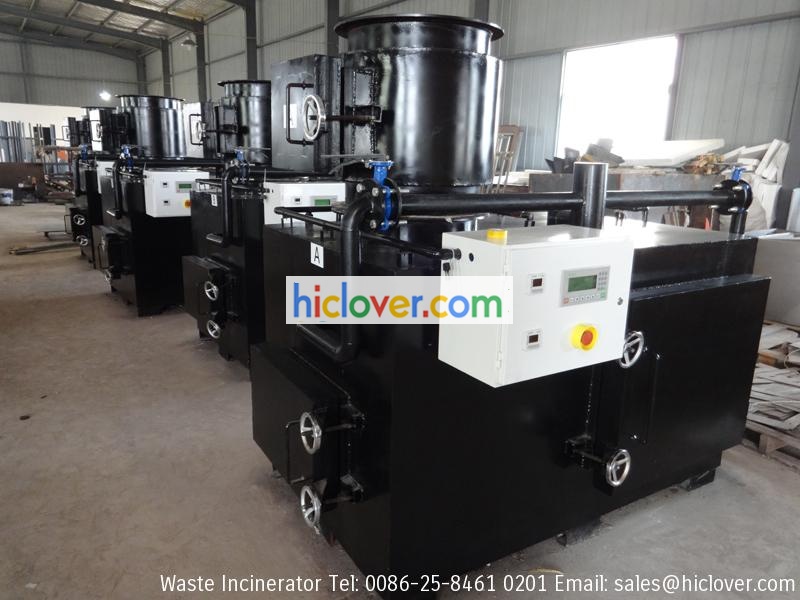
1.A chamber of post combustion of gases
A burner of combustion of gases,
A device of injection of air allowing a total re-combustion of gases,
A device of air inlet of cooling of waste gases,
A sheath of evacuation of the gases burnt,
Carcass in strong sheet steel with support of connection
Composition of the refractory;
Refractory concrete:
Thickness :>150mm
Nature: 65%% of Al203
Insulate in fibrous panels:
Thickness: >85mm
Nature: Calcium
Burner with fuel, mono-bloc casting guiding type with horizontal flame, lighting and safety of electronic ignition, permanent ventilation,
electromagnetic sluice gate of regulation and isolating valve.
A secondary injection of air to ensure perfect oxygen content.
2.A control box ensuring the complete cycle of combustion.
3.Fan:
Electro-ventilator distributing the secondary air, the regulation of the air flow being carried out by valves and following the control of
the automatic cycle.
4.Controls and regulations:
Control box watertight to dust, including:
A switch circuit breaker for each engine (ventilators and burners).
A timer with adjustable temporization for the regulation of each burner.
A regulator with digital watching for the temperature of combustion.
A regulator with digital watching for the temperature of post-combustion.
Electric box.
5.The de-ashing must be done in the bottom of the combustion chamber or the de-ashing should be automatic or manual batch de-ashing.
6.Process filtering system: scrubber to be mentioned as optional
7.Emission standards compliance: BS 3316 or equivalent standard
8.Capacity to treat plastic: not less than 40% by weight
9.CE manufacturing compliance: BS EN 746-2-1997

