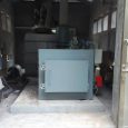
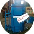
medical incinerator primary combustion price

Our normal activities generates 2-5 tons of assorted waste materials per day which range from condemned carcasses, and medical incinerator primary combustion price

other wastes all which need to be incinerated at above 800Centigrade measured flue exhaust gas.To be used by small

hospitals and clinics to safely dispose of infectious and pathological wastes.

Load Capacity in the range of up to 200 kg
– Burning Rate approx. 50kg/Hour –

Incinerators to be very effective, fuel efficient with high / low capacity burn rates
and to be designed to meet the Norms of Pollution Control / DEFRA, etc. Technology:

Temperature Controlled Burner. Heavy-duty casing, to be a quality, rugged, reliable, economical Medical Waste

Incinerator with relevant control, easy to operate and self-contained. Type of Fuel: Diesel / Oil or Petrol.
Units to be pre-assembled, pre-piped, pre-wired & tested before Transport / Export.

Within the framework of an environmental and medical equipment & technology consultation and joint purchasing, this

Procurement Bureau invites applicants for pre-qualification in the aim of primarily selecting capable companies to bid

for the above tender.
The supply will comprise the special equipment for effective waste management as mentioned above for a new private

environment contract management company with planned operations 2013 in Indonesia and Thailand, and 2014 in West & East

Malaysia to carry out those professional services in order to comply with the governments safety disposal requirements

for medical and hospital, clinical waste in the region and to meet the higher technical standard in this particular

field.small incinerators with filter (with least minimum pollution) for burning/combusting 5kg/hr, 10kg/hr, 15 kg/hr,

20kg/hr, 25kg/hr to 50kg/hr and 300kg/hr of SOLID ORGANIC DRY AND WET NON-HAZARDUOUS of any kind (including hospital

wastes) per day or per hour. Should it be with no smoke, no fumes, no odour (smell), no dust, no emission of solid

particles and with least minimum pollution (within national and international standards). Must be environmentally

healthy and acceptable with international standards. Should not be with water scrubbers. Ash contents after burning

should be 3-4%.

incinerator plant specification


(b) Change:
( I) Mains shift is an usual problem, the efficiency needs to be affected by this problem a tolerance of ± 15 percent or more at both the nominal voltage should be permitted.
( ii) Keys Cut-off (black outside ) is a typical issue. Where essential, Uninterrupted Power Supply (UPS) System must be included to prevent damages of gear as an outcome of abrupt disruption in electricity distribution.
( iii) There are spikes not automatically from the keys supply nonetheless results when certain plants or apparatus began.
( iv) Vendors must consequently verify to make sure their power distribution systems won’t be impacted by the above conditions.

two ) Supply Of Water
a) Top grade: the mains distribution is tough water. B ) Anxiety: this changes and associated with regular cut off. Where required, the provider should add pumps or boosters to conquer this situation.
Demands

3) Temperature amount: ambient temperature arrays between 21– 450 C or more in poorly ventilated areas. The most popular month of the year is March. Environmental temperature level can be such that poor rubber as well as plastic goods can handily melt or warped. Prospective buyers must make sure all products will have the ability to survive these temperatures

4) Humidity: moisture is normally high concerning 65– 90%. Electronic devices must be secured to prevent the effect of condensation. Dust enter equipment and clogs up filters. Extra security needs to be supplied where essential in addition to where appropriate added filters offered to last not less than 5 years continuous use.

6) Vermin: these can also be offered in addition to occasionally take part in gear to chew cable televisions in addition to urine on boards to create short circuit. This may be stopped by offering vermin guard where required to prevent entrance of these catastrophic animals.
B ) All software application programs from the suggested apparatus should stay in English
language
c) All manuals have to be in English language.

9) Each of the apparatus supplied need to be offered with customer along with technical handbooks. Guidelines on their usage, storage area and also alternative must be clearly indicated from the manuals and also where necessary, on the apparatus.

10) Where appropriate that the following will apply:
a) Electrical Security I) The system needs to be supplied with a line (electricity ) cord of durability that is acceptable, quality, length, and ampacity and also needs to be protected with appropriate stress reliefs.
Ii) The apparatus needs to comprise the bidder or supplier must provide, power plugs that are adequate for the maximum voltage as well as current of the unit.
Iii) The frame needs to be established and grounding resistance needs to not go beyond 0.15 ohm.
Iv) If the system is dual protected, it should be labeled.
V) Electrical leakage current in the frame of the device shouldn’t exceed
500µA a IEC 601-1 b) Outcomes of Fluids

Area VI. Requires 2-84

I) Individual and also operator safety and security in addition to system functionality need to not be detrimentally influenced by fluid spills.
Ii) If the unit is impacted, it needs to fall short safely.

c) Overcurrent Security
I) reduction of electricity to various other devices on the specific same branch circuit due to internal gear errors need to be averted by using integrates or breaker that are labeled in addition to simple to convert or replace.
Ii) If merges are made use of, a spare fuse must be offered in a identified holder situated alongside the primary fuse holder. Long-term markings near each fuse holder must signify fuse scores.

d) Line Voltage Variation
I) The apparatus must operate satisfactorily online voltages from -12.5% to +8%.
Of the little line voltage of 220Volts.
Ii) The system should not be harmed by voltages from -21% to +12.5% of the little line voltage of 220Volts. I ) The apparatus ’s functionality should not be affected by EMI emitted or ran together with the high-voltage line from yet another tool.
Ii) If the system is impacted, it ought to fail securely.

f) Alarms.
I ) The unit needs to have visual or audible alarm systems to advise motorists of any sort of system fault that may trigger damaging or incorrect outcomes.
Ii) Audible and/or aesthetic signs should trigger when the display reading gets to and remains in the alert system limitation.
Iii) All alerts must be totally clarified from the motorist ’s handbook.

gram ) Audible Alarms.
I ) Audible alarms need to be distinct in addition to easily identified.
Ii) Distinct alarm systems must be enabled when the unit is triggered (i.e., the default volume need to not be set to OFF) and should be clearly audible at any sort of quantity setting.
Iii) If the alarm system quantity is flexible, it should not be possible to turn down the volume so reduced it is not most likely to be heard.
Iv) Although an audible-alarm silence is acceptable, the alert should reoccur automatically if the condition is not remedied.
V) If an alarm is silenced, a visual display should clearly indicate which alarm system is disabled.

h) Visual Alarm systems.
I ) Visual alert systems should be easy to comprehend.

2-85 Area VI. Requirements

ii) The aesthetic alert must define to the trouble and stay on up until the alert system problem is fixed; it should be impossible to shut off the aesthetic alarm.

I) Building and construction Top quality.
I) The system should have no sharp edges.
Ii) All external components should be safely mounted.
Iii) The system ought to be protected and provide appropriate protection versus relocating and stimulated parts.
Iv) The system ought to be well constructed with durable products to resist common cleaning and abuse.
V) Switches, manages, in addition to other controls must be made for conditions of heavy usage.
Vi) Wiring and also tubing should be well organized in addition to packaged, if ideal. Vii) Mechanical, electrical, in addition to pneumatic terminators, sockets, connectors, as well as.
Solder joints should be designed to stop liquid infiltration, inaccurate links, and also mismating of suitable and couplings.
Viii) Connections must be safe to withstand accidental disconnection and ought to maintain sterility, when ideal. I ) The controllers (i.e., switches over, knobs, and so on) need to be visible in addition to plainly ascertained, and also their features must be self-evident.
Ii) Tool style should prevent misconception of display screens and also control setups.
Iii) Buttons and also controls should be shielded against unexpected setup alterations (e.g., due to a man cleaning versus the board ).
Iv) Controls needs to be sealed versus penetration of liquids.

k) Classifying.
I) Labels in addition to markings should be apparent and also readable.
Ii) Labels and also markings must be resilient enough to withstand regular cleaning along with regular wear.
Iii) Proper caution legends should be supplied on the unit.

l) Ease of Usage and upkeep.
I) The system must be basic to learn how to utilize, operate, and also keep.
Ii) The system must have pre-programmed operating instructions contained on or with the unit (e.g., on a laminated card connected to the device ).
Iii) The system needs to be easy to clean, sanitize, and/or decontaminate, as ideal. Iv) The unit ought to be made for easy accessibility to serviceable components.

m) Particular upkeep tools, spare-parts in addition to consummables.
I) Where required or needed, the provider must consist of any sort of special devices required for the maintenance of the suggested devices.
Ii) Each apparatus should be offered together with the suggested spare-parts

Area VI. Demands 2-86

needed for preventative upkeep for five years and also where essential consist of distribution of advised spare-parts for rehabilitative maintenance.
N ) Training.
I) The provider is required to supply adequate training on every apparatus on the appropriate usage and procedure of the tools.
Ii) Likewise, distributors are required to supply adequate supplier’s training about the installation and also maintenance( both preventative and restorative).
O) Packaging and also Storage Space Problems of Tools.
I ) The devices and components should resist temperature and also moisture extremes most likely to be experienced during storage area and also transportation.
Ii) The maker should advise treatments for storage of the equipment.

j) Controls.
i) The controls (i.e., switches over, knobs, and so on) need to be visible as well as plainly determined, and also their features must be self-evident.
ii) Tool style ought to avoid misconception of display screens and also control setups.
iii) Buttons and also controls ought to be shielded against unexpected setup modifications (e.g., because of a person cleaning versus the panel).
iv) Controls needs to be sealed versus penetration of liquids.

k) Classifying.
i) Labels as well as markings ought to be clear and also readable.
ii) Labels and also markings must be resilient enough to endure regular cleaning and also regular wear.
iii) Proper caution legends ought to be supplied on the unit.

l) Ease of Usage and upkeep.
i) The system must be basic to learn to utilize, operate, and also keep.
ii) The system must have abbreviated operating directions included on or with the unit (e.g., on a laminated card attached to the unit).
iii) The device needs to be simple to clean, sanitize, and/or decontaminate, as ideal. iv) The unit ought to be created for simple accessibility to serviceable components.

m) Special upkeep tools, spare-parts as well as consummables.
i) Where needed or needed, the provider has to consist of any kind of special devices required for the maintenance of the suggested devices.
ii) Each devices should be provided with the suggested spare-parts

Area VI. Demands 2-86

required for precautionary upkeep for 5 years and also where necessary consist of supply of advised spare-parts for rehabilitative maintenance.
n) Training.
i) The supplier is needed to supply adequate training on each devices on the appropriate usage and procedure of the tools.
ii) Similarly, distributors are required to provide adequate supplier’s training on the installation and also maintenance( both preventative and restorative).
o) Packaging and also Storage Space Problems of Tools.
i) The devices and elements should stand up to temperature and also moisture extremes most likely to be experienced throughout storage space and also transportation.
ii) The maker should advise treatments for storage of the equipment.


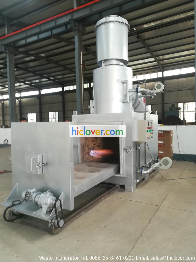
Medical Incinerator


Product Description

Nanjing Clover Medical Technology Co., Ltd..

Items Specification
YDC Model YD-10C / YD-20C / YD-30C / YD-50C
Main Product List Primary Combustion Chamber
Secondary Combustion Chamber
Mix Combustion Chamber
Smoke Filter Chamber
Incinerator Common Control Case
Stainless Steel Chimney
Italy oil/gas burner: 02 units
Oil Tank (if oil fuel)

So, why we still use incinerator?  To begin with, for your medical waste in the hospital, the pyrolytic incinerators is greatest remedy up to now. Pyrolytic technology can kill the virus, pollution management.  Secondly, for human body, pet animal, in most countries and areas, we incinirator producer in china, incinrator 100 kg manufecturar, incneratorbyburnerlpg, inconeration equipment maker in china, industrial incinerators in china, want to cremation them. This is the service at the process of society growth, and ceremonies to commemorate the disappearance of life.

small scale incinerator of burning capacity

Poultry Incinerator – 400 kgs feed per day.a small scale incinerator of burning capacity 30kg/hr=1No. Note that it should be portable as this is meant for oil fields work on tented camps. Also it has to be diesel operated as our location is remote. 150!kg per hour LPG smokeless incinerator to be used at the international airport. This is a requirement bu the bio security that all international flights need all rubbish burnt within a set time.Required load capacity is 150Kg
Chamber – Primar 900 liters Secondary: 300Litres
Chimney 8M
Burning Rate: 50kgs/hr    Yes
Feed Capacity: 150kgs    Yes
Primary Combustion Chamber: 900 litres    Yes
Secondary Combustion Chamber: 300 litres    Yes
Mix Combustion Chamber: Yes    Yes
Smoke Filter Chamber: Yes    Yes
Feed Mode: Manual    Yes
Power: 0.7Kw    Yes
Fuel Type: Diesel Oil/ Natural Gas/LPG    Yes. Different Price if oil or gas fuel.
Internal Dimensions: 120 x 90 x 85cm (primary chamber)    Yes
External Dimensions: 200 x 160 x 310cm (without chimney)    Yes
Burning Efficiency: >98%    Yes

Numerous Sorts Of Burners


contaminated materials high temperature burners for the treatment of contaminateds materials. The waste will definitely be blended, including medical, oily wastes, woods as well as lab wastes. Key burning
Diesel/LPG/LNG burning primary burning chamber/primary burning location
Extra burning
House time in the second chamber very little less than 2 secs
Both primary and also the second temperature level degrees protected till all the waste has actually been entirely combusted
Chimney
Smokeshaft with a minimal altitude of 4 meters above ground level
Minimum leave rate of the discharges not less than 10 metres/second
Temperature level Cautions
Unique and/or obvious alarm to caution the vehicle driver when the additional temperature degree drops to below the called for temperature level
General
Control box that can be separated and positioned on separate stand at the very least 1.5 meters from incinerator at around 1.6 meter height

Burner variation A.
Burn Price 65kg/h minimum.
Weight (kg), please suggest:.
Second Chamber.
Gas Retention Time – – – – 2 Seconds. Power Supply – for – Control Box – 220V-240V 50Hz solitary phase.
10m Tube Pipeline, suggest size. I000 Litre Gas Container+ Pipeline System, show volume. Included smokeshaft expansion
, indicate elevation. Service warranty, recommend no of years

Heater style B. Burn Price 150kg/h minimum.
Gas Retention Time – – 2 Secs. Diesel/LPG/LNG, please indicate. Minimum operating temperature level 920 ° C, please suggest.
10m Pipeline Pipeline, show dimension. I000 Litre Gas Container+ Pipe System, reveal quantity. Extra smokeshaft growth, show elevation.
Guarantee, reveal no of years

Heater variation C.
Burn Rate 250kg/h minimum.
Weight (kg) please indicate:.
2nd Chamber.
Gas Retention Time 2 Secs.
Fuel Diesel/LPG/LNG, please program.
Power Supply for Control Box 220V-240V 50Hz solitary phase.
Minimum running temperature 920 ° C, please show.
One year Spare Parts Package for total maintainability.
10m Tube Pipe, recommend length.
I000 Litre Gas Container + Pipe System, reveal amount.
Added smokeshaft growth, reveal elevation.
Service guarantee, suggest no of years

Whole lot 4– – High Temperature Waste Incinerator.
HTW Incinerator layout D. Burn Cost – – 150kg/hour minimum.
Weight (kg), please show:.
Additional Chamber.
Gas Retention Time 2 Seconds.
Gas Diesel/LPG/LNG, please indicate.
Power Supply for Control Box 220V-240V, single stage 50-60Hz.
Minimum operating temperature level 1200 ° C, please show.
One year Spare Elements Plan for overall maintainability.
10m Hose pipe Pipeline, show length.
1000 Litre Gas Storage Tank + Pipe System, suggest volume.
Additional smokeshaft development, suggest elevation.
Service warranty, reveal no of years

Great deal 5– – Mobile Burner.
Mobile Incinerator version E. Burn Price 50kg/h minimum. Weight (kg), please show:.
Gas – Retention Time – – 2 Seconds. Gas – Diesel/LPG/LNG, please show. Minimum running temperature level 850 ° C, please suggest.
Assurance, suggest no of years

Lot 6– – Mobile Incinerator.
Mobile Heater design F. Burn Price 100kg/h minimum. Weight( kg), please recommend:.
Extra Chamber.
Gas Retention Time – – – – 2 Secs. Gas – Diesel/LPG/LNG, please suggest –. Power Supply – for – Control Box – 220V-240V 50Hz single stage. Minimum running temperature 850 ° C, please suggest. One year Spare Elements Package for full maintainability.
10m Tube Pipe, suggest length.
1000 Litre Fuel Storage Tank + Pipeline System, suggest quantity.
Additional smokeshaft growth, suggest altitude.
Assurance, show no of years

Good deal 7– – Heat Waste Mobile Burner.
HTW Mobile Incinerator style G.
Burn Rate 100kg/h minimum.
Weight (kg), please indicate:.
2nd Chamber.
Gas Retention Time – – – – 2 Secs. Gas – Diesel/LPG/LNG, please indicate. Power Supply for Control Box – – – – 220V-240V 50Hz solitary stage.
Minimum operating temperature 1200 ° C, please show.
One year Spare Parts Prepare for total maintainability.
10m Tube Pipeline, suggest size.
1000 Litre Gas Tank + Pipe System, show amount.
Additional chimney extension, recommend altitude


an incinerator for our dental clinics

an incinerator for our dental clinics.The incinerator must comply with ” Technical Standard NTON 05-015-02 Management and Solid Waste Disposal Hazardous co go ” , in addition to meeting international standards functionality standards for new stationary sources and emissions from the Environmental Protection Agency United States ( Environmental Protection Agency EPA ) Incinerators Medical and Hospital infectious waste ( HMIWI its acronym in English ) and the standards of the World Health Organization (WHO ) .

According to point 8.5.1.3 of the NTON 05-015-02 incinerator must have the following:

” Incinerators equipped with a camera primary and a secondary combustion , equipped with burners capable of achieving complete combustion of waste and widespread destruction of harmful and toxic chemicals (dioxins and furans among others) , attached to the solid waste bioinfectious .

a) primary combustion chamber , it requires a temperature of 800 ° C and one hour dwell to be destroyed waste produced ash and gas , including dioxins can generate cancer is found .

b ) In the secondary combustion chamber must reach temperatures around 1,100º C and must be operated with a residence time of the flue gases of a minimum of two seconds. To treat gas flow and entrained particles , before being released into the atmosphere , should be added towers chemical washing , cyclones , filters . ”

The incinerator installed must comply with the design to ensure the destruction of all hazardous , biological , industrial waste and others. Combustion ” PYROLYTIC ” allows control of the gasification of waste and avoid significant release of black smoke and fine powder during loading . It also allows , regular and complete combustion of the waste.

The main advantages are a controlled combustion that guarantees the absence of smoke, color , smell or dust . It is also automatic, so you do not need supervision and has a low fuel consumption .

The incinerator includes:

1. A combustion chamber :
a. watertight door for manual loading of waste.
b . A burner start is limited to inflammation of waste .

2. A camera post-combustion gases :
a. burner combustion , low power .
b . An injection device air for total re- combustion of the gases .

c . An input device cooling air of the combustion gases.
d . A smoke evacuation duct .

3. A control panel ensuring complete combustion cycle .

The incinerator meets as indicated on waste incineration .
They will not burn plastics, packaging except that the amount so small that gases need not receive any treatment, secondary combustion chamber to 1100C handles everything ..

The chimney is 350 mm inner diameter and a height of 8.13m will with hatch analysis.

Combustion chamber

• The combustion chamber is thick steel plate (3 to 10 mm ) with reinforcements, specially built .
• Front loading with watertight door mounted on hinges, locking screw wheel , flexible gasket and an insulating refractory lined .
• An internal lining of refractory concrete containing 42% of H² 03 (alumina ) and 100 mm thick walls.
• fibrous insulation panels made of calcium silicate with a thickness of 75mm .
• Automatic Burner ( diesel or gas must be specified in the order ) with flames diving in one piece monoblock with an electronic ignition system , permanent ventilation control valve and isolation valve.

• combustion floor made in carborundum , preventing binding of glass and slag.

Afterburner gases

• The afterburner is strong sheet steel flange connection.
• Internal filling refractory concrete with very high alumina content ( 65 % H² 03) and a thickness of 150 mm .
• thermal insulation panels made of fibrous silicates and calcium with a thickness of 85 mm .
• diesel or gas burner (must be specified in the order ) , monobloc horizontal flame , electronic ignition , safe , permanent ventilation , control valve and isolation valve.
• air injection nozzles made of refractory steel with a flow control valve.
• These nozzles are specially designed and patented by ATI to guarantee very low hydrocarbon emissions.
• A secondary air injection is scheduled and ensures perfect oxygen content.
• Fan distribution primary and secondary air , the air flow regulation is effected by means of valves and actuators on automatic cycle commands.

Control and regulation
Control Panel dustproof , painted sheet with baked paint comprising:
• A circuit breaker switch for each motor ( fans and burners) .
• A timer adjustable time delay for each burner control .
• A regulator with a digital display for the combustion temperature .
• A controller with digital display for temperature afterburner .
• The electrical panel meets current standard. For removal of ash , a squeegee metal pan with handles

Painting
• Color : Light + dark blue.
• Special high temperature.

OPERATION

The operation thereof is as follows:

• Charging waste.
• Close the door.
• Obtaining the combustion cycle during which no monitoring service ( duration 2 hours ) is required.

The combustion cycle automatically ensures :
• Starting the secondary air fan.

After 10 minutes, the afterburner is temperature:

•Turning on the automatic burner combustion chamber , which guarantees the output of the gasification of waste. The operating time of the burner is programmable according to the type of waste, using an adjustable mechanical timer from 1-60 minutes.
• Automatic start of combustion air fan.

After 2 hours , the end of ” combustion cycle ” automatically guarantee :

• The closure of primary air servomotor .
• The post-combustion burner off.

During charging , opening the door automatically ensures immediate shutdown fan primary and secondary air . At the end of the combustion cycle the fan primary / secondary air and burner continues to run for 2 hours to protect the burners and to cool the oven . After this time the program automatically turns off the installation completely .

FUEL USE

This installation shall take for operation of diesel with the following characteristics :

Density at 15 ° C (max / min ) 0.88 / 0.82 kg / l
Weight sulfur 0.2 % max.
Kinematic viscosity at 40 ° c ( min / max) 2 / 4.5 mm2 / s
Point above 55C inflammation.
Cold filter plugging point -10 ° C max.

DIESEL AND FOOD TANK BURNER

The fuel tank will be located annexed to the dugout roof incinerator in a bund and have the following characteristics :

• Capacity: 1,200 liters
• Made of sheet steel for simple wall installation cubeto
• Output for ventilation diameter 1 ½ ”
• Pressure gauge and filler cap
• Meter and level switch

The incinerator has a consumption of 16.2 liters of diesel hour to burn waste generated operation 10 hours a week expected in two burning , so that autonomy will be 7.5 weeks . The reservoir will have an outlet and an inlet for return. Pipes for oil will drive the black steel pipe with longitudinal electric resistance welded 3/4 ” DN 20mm diameter . In the tank outlet pipe retainer debris filter , with aluminum body is placed , aluminum cup and stainless steel sieve with holes 100 microns in diameter .advise on the consumption rates, is that for both chambers, or per chamber?

Large Capacity Animal Pet Cremation HICLOVER Model A1500 with E-Power Automobile.Door


Large Capacity Animal Pet Cremation HICLOVER Model A1500 with E-Power Auto. Door

Model

A1500

Internal Dimensions

150 x 100 x 96cm

Suit for Animal

Cat – yes

Dog – yes

Pig – Little

Cow – Little

Main Product List

Primary Combustion Chamber

Secondary Combustion Chamber

Mix-Combustion Chamber

Smoke Filter Chamber

Incinerator Control Case

Chimney:10.0Meters

*(Update to Stainless Steel, free cost)

Italy oil/gas burner: 03 sets

Oil Tank (if Petroleum fuel): 500Liters

Design for Clients Cremation Business

Movable platform & Automobile.

Independent Position for Little Pet


HICLOVER – Medical Environmental 


Waste Incinerators
Medical Waste Incinerator
Pet Animal Cremation
Solid Waste Incinerator

Tel:  +86-25-8461 0201   
Mobile: +86-13813931455(whatsapp/wechat)
Website: www.hiclover.com  
Email: [email protected]
Email: [email protected]  
Nanjing Clover Medical Technology Co.,Ltd.


hog incinerators


The purpose of the start-up burner is to ignite waste materials and to maintain the prescribed minimum

temperature in the primary chamber. It shall be mounted in the lower part of the primary chamber.


  1. The start-up burner shall function automatically when:-


–      Pre-heating is completed, or after reaching the adjustable minimum temperature in the thermal reactor.


–      The temperature in the primary chamber has dropped below the adjustable minimum value (e.g. 300?C). This can

occur when a lot of damp waste material is to be combusted.


–     The start-up burner shall be of one-stage burner with pre-ventilation, working on the principle of an oil

atomizer for diesel oil, consisting of:-


–      Fan housing with adjustable air intake.


–      Air closure damper with actuating drive


–      Burner tube with burner connection and insulating flanges


–      Burner plate with automatic oil firing sequence control, ignition transformer


–      Electric nozzle rod with quick closing gate valve, electrode block, baffle plate.


  1. The mounting point of the waste ignition burner shall be fitted with a manually operated sliding closure plate

to protect the burner head when the flame is not in use. The slide plate shall be interlocked with the burner ignition

controls to provide operation of the burner when the slide plate is not in the fully open position.


The integral burner air fan shall be wired for continuous running.


  1. Reactor Burner


The purpose of the reactor burner is to ignite low temperature carbonization gases and to maintain the prescribed

minimum temperature in the thermal reactor at all times but mainly during periods when the energy content of the

carbonization gases is low (pre-heat, post combustion phase). It shall be mounted in the entrance area of the thermal

reactor.


The reactor burner shall modulate between partial load and full load and automatically function when:


–      The temperature in the thermal reactor drops below the adjustable minimum operating value (e.g. 1000?C) (full

load)